
News Release from SKF Lubrication Systems Germany GmbH
Wind Industry Profile of
Company of the Day - Lincoln GmbH - Centralized Lubrication Systems in Wind Turbines
Centralized lubrication systems are being used more and more in onshore and offshore wind turbines. The main objectives are to simplify servicing, cut costs, reduce wear and tear and increase the intervals between scheduled services.
Today it is essential to increase the life expectancy of wind turbines and reduce the costs of operation. One of the greatest past problems in operating wind turbines was the fact that some manufacturers did not provide continuous lubrication. Adding small quantities of lubricant at regular intervals constantly renews the film of lubricant on the bearing components, reduces friction in the bearings, reduces running noise and prevents the ingress of contaminants. The bearings therefore operate more smoothly for longer.
Some manufacturers of wind turbines have been using lubrication systems since the end of the 1980s. Today, centralized lubrication systems are being considered by more and more manufacturers. To greatly simplify the process of supplying lubricant to the lubrication points around the blade bearings, the first progressive distributors and single-nipple systems were installed on the blade bearings. Centralization reduced the number of lubrication points per blade bearing from nine or more to just one. Automatic continual lubrication via a progressive centralized lubrication system was the next stage, and this is now being used in numer-ous wind power plants.
The progressive centralized lubrication system
In the progressive CLS, the lubricant is piped to the distributor from the reservoir of the centralized lubrication pump. The lubricant is apportioned there and forwarded via the distributor outlets with no loss of volume. One outlet must be fully charged before the next outlet can be supplied. As long as the distributor is supplied with lubricant it will distribute it to the lubrication points to which it is connected. This principle of a constantly reversing distributor means that correct operation can be easily monitored, for example with an electrical initiator. The distributor that is connected directly downstream of the pump can be connected to further distributors, either as sub-distributors or as lubrication points. Arrangements of main distribu-tors and sub-distributors should have no more than two generations of distributors.
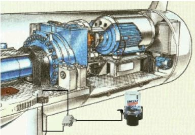
The CLSs for supplying the blade bearings and the blade adjustment system are installed in the nose. Depending on the concept of the wind power plant, it may only be necessary to use the centralized lubrication pump on the blade bearings. The CLSs for the main bearings, yaw bearings, yaw gear drive and generator on the other hand are installed in the gondola. There are no prob-lems associated with locating a centralized lubrication pump there. However in the area of the nose a different technical specification is needed for the pump. The movement of the rotor, which is also served by the centralized lubrication pumps in this area, calls for a solution that reliably supplies the lubricant to the pump element of the centralized lubrication pump in all positions.
 Control of the CLS
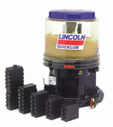
There are different ways of controlling the CLS. Series 203 and 301 pumps, for example, have integrated control boards. There are different control concepts, for example for microprocessor control or control of operating time and pause time. The CLS can also be controlled by the plant's own controllers. This integration of all the switching, control and monitoring processes of the CLS in the plant's own process automation system will soon become the industry stan-dard. It therefore makes sense to use pump systems that already comply with this standard.
Gear drive lubrication
Supply to the gear drives is important for manufacturers and operators of wind power plants. Depending on the type of plant, there is a minimum of one and a maximum of four open gear drives in wind power plants. The yaw drive is common to all of them. This is an open gear drive that aligns the gondola in the direction of the wind. If the rotor blades also have an open gear drive there are three further gear drives in the nose. The yaw gear drive is relatively unproblematic compared with rotor blade adjustment as every point on the gear drive can generally be reached with a lubricating system.
The situation is different with rotor blade ad-justment. Here only a 90° cog segment is actually used. Things are made more difficult by the fact that for around 90 percent of the production time of a wind power plant the rotor blades remain in what is known as the 0° setting and are adjusted by only minimal amounts. Two to three cogs of the open gear drive are therefore exposed to extremely high loads for 90 percent of the time that the wind power plant is in produc-tion. Conventional lubrication of this cog segment can therefore only be achieved if the rotor blades pass through the complete 90° segment during a maintenance ses-sion. However, as maintenance normally cannot be carried out without the power plant being shut down there are only two options for lubricating the rotor blade adjust-ment gear:
- Lubrication during the natural idle phases (no wind)
- Compulsory maintenance intervals, as-sociated with additional loss of production
The idea of adapting the lubrication cycle to actual production is attractive to operators but not at all to designers or maintenance staff. The fact is that during extended periods of windy conditions production phases may be extremely long. These periods tend to be longer for offshore plants than for on-shore installations. In such cases there is a possibility that the lubricating film will fail before the end of the production phase, leading to damage to the gear drive. The cost of replacing a gear drive is enormous and far exceeds the costs involved in shutting down a wind power plant. The lesser of two evils is therefore to have a compulsory maintenance interval with an accepted loss of production.
Mechanical gear drive lubrication
The design of the progressive system for gear drive lubrication is essentially classic.
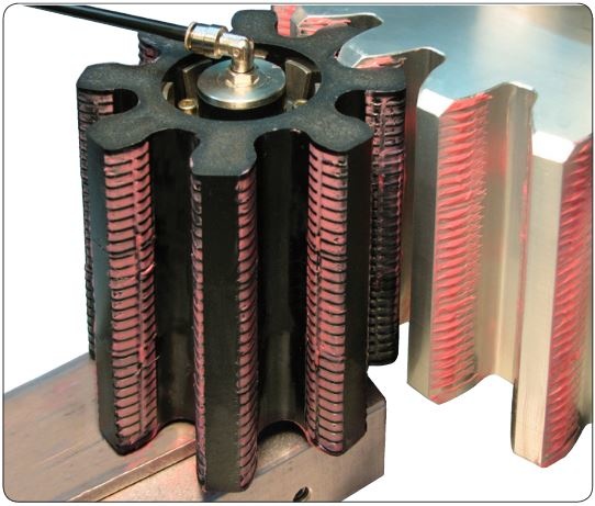
However the lubricant is not supplied to a lubrication point but to a lubricating pinion. In this case it is a felt pinion whose module synchronizes with that of the gear drive or the drive pinion. The felt gear wheel rotates under zero load on an axle which is connected to a fastening plate. The axle is hollow-bored and has lubrication connections on both sides. The lubricant is supplied to the transfer channels in the felt pinion via the axle and flows out on the tooth flanks of the felt pinion. When the gears engage the lubricant is then transferred to the gear drive or the drive pinion. The felt pinion is adapted to the geometry of the engaging gear.
Depending on the design, a lubricating pin-ion can be attached either to the drive pinion or directly to the gear drive in the area of blade adjustment. In the former case, it should be remembered that the lubricant is transferred to the gear drive only indirectly. In the latter case, lubricant can be applied directly to the tooth flanks over most of the 90° segment. If only one lubricating pinion per blade adjustment is used then it is possible also to attach only on one side of the drive pinion, so indirect transfer through the drive pinion to the other segment side is also used here. Overall, lubricating pinions are a workable solution for supplying open gear drives. Many trials have shown that there are problems with the lubricants. To date, there have only been two adhesive lubricants that have proved to be suitable and have not dripped off.
Airless spraying
Spraying is one way of transferring lubricant to a tooth flank that has proved to be successful in a large number of applications. In conventional spraying, the lubricant is sprayed on the tooth flank through wide-jet nozzles with the aid of compressed air. With optimally aligned nozzles it is possible to achieve excellent spray patterns and cover the tooth flanks perfectly with lubricant. Unfortunately, there is still no compressed air available on a wind power plant, and installing a suitable compressor is also difficult. Accurate alignment of the lubricant nozzles combined with clean application of lubricant without the use of air in a process known as airless spraying is therefore a suitable solution to the problem of reliably supplying the highly loaded gear teeth during meshing of the gears.
The lubricant is conveyed from the centralized lubrication pump to a pressuriser. The connection between the pressuriser and the airless nozzle is sealed by a 2/2 way valve. At the time of the lubricating cycle the valve opens and the lubricant is sprayed under high pressure through the airless nozzle onto the tooth flank. Since application of the lubricant can take place in the gap between the drive pinion and the blade gear drive a lubrication cycle can be completed without shutting down the plant. Any 10° swing in the rotor blades that may be necessary can be made during proproduction. In future, airless spraying will be the solution to the problems of lubricating blade adjustment. Both airless and air-based methods are possible for the yaw drive. In both applications a larger number of adhesive lubricants have proved to be usable. The amount of lubricant needed in air spraying is minimal.
Generator bearing lubrication
Because of the small amount on bearing points, the short line lengths and the small amount of lubricant needed for the generator bearings it is not necessary to use a CLS as described above. A type 301 centralized lubrication pump is recommended for lubricating the generator bearings.
It can be called a small CLS because in addition to the actual pump component it has an electrically monitored progressive dis-tributor. The pump element is directly con-nected to the distributor and is protected by an integrated pressure limiting valve. All the lubricating points are directly connected to the outlets of the distributor. Here too the CLS can be controlled by an integrated con-trol board or an external controller in the electrical system of the plant.
It is clear then that the use of a continual automatic lubrication system brings consid-erable competitive advantages in operating wind power plants. Even though a large proportion of the plants already have CLSs, manufacturers and operators should bear in mind in this rapidly expanding market for wind power that new investment in onshore and more particularly in offshore wind farms is associated with longer service life for the plants thanks to the comprehensive use of centralized lubrication systems.
If you would like to recieve our Newsletter or find out more about what w3.windfair.net has to offer. Please, do not hesitate to contact Trevor Sievert at ts@windfair.net.
w3.windfair.net is the largest international B2B Internet platform in wind energy – ultimately designed for connecting wind energy enthusiasts and companies across the globe!
- Source:
- Lincoln GmbH
- Author:
- Edited by Trevor Sievert, Online Editorial Journalist / by Lincoln GmbH Staff
- Email:
- Michael.Slembeck@skf.com
- Link:
- www.lincolnindustrial.de/...