News Release from windfair.net
Wind Industry Profile of
Inside Offshore Projects - The Walney Offshore Windfarm
ABOUT THE WALNEY OFFSHORE WINDFARM
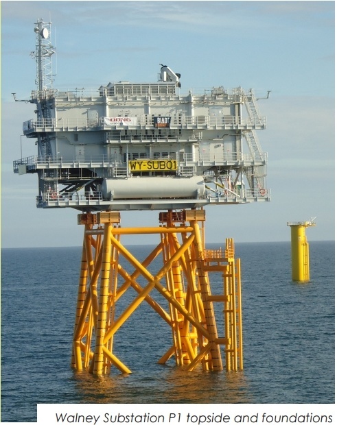
The Walney Offshore Windfarm is 15km from the coastline of Walney Island in a north west to southeasterly direction covering approximately 73km2 . The Walney 1 Windfarm consists of 51 turbines each with a capacity of 3.6MW, powering 160,000 UK households. When Walney 2 comes online the total will increase to 320,000 UK households. The windfarm turbine array consists of a number of rows of wind turbines connected by one cable from Walney 1 and one from Walney 2 which will carry the power to shore. The substation has a typical four leg jacket style foundation. The foundations for the turbines are monopiles.
FOUNDATION DESCRIPTION
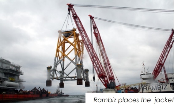
The jacket is of steel construction with 4 legs. It is secured to the sea bed by 4 main piles driven through the sleeves. The piles are OD 1,829mm driven through sleeves of ID 1,990mm. The connection between the driven piles and the jacket was made by injecting a cement grout into the annulus around each pile. Thus, the structural integrity of the platform was dependent on the correct placement and retention of good quality grout in the annulus of each pile. The lower end of each annulus was equipped with twin grout seals to retain the grout. Each sleeve had a primary and secondary grout line through which grout could be pumped into the annulus. A conventional grouting system has been designed for the installation of the jacket. The pile sleeves are equipped with primary and secondary grout lines terminating at elevation +16.3m. The lower end of each pile sleeve is equipped with an Oil States type grout seal, the purpose of which is the retention of the grout in the annulus whilst it is curing.
QUALITY CONTROL
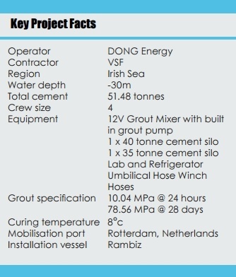
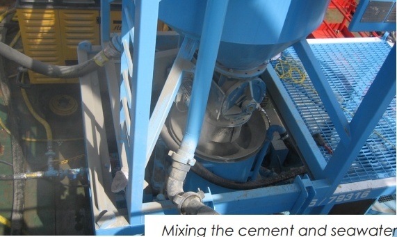
During mixing, the grout density was monitored at intervals using a pressurised slurry density balance. Three samples were taken during the grouting of each annulus: one after 10 bbl had been pumped, one halfway through grouting, and one towards the end of grouting. For each sample the density was recorded and three 75mm grout cubes were manufactured. Each cube was marked to identify the platform, leg number, time and date of casting and the specific gravity. The samples were cured underwater at 8o c ± 0.2o c. THE MIXING SYSTEM Cement was stored in bulk pressurised silos and delivered to a surge tank above the mixer. Water was delivered to the mixer from the barge fire main pipe work and measured through a water flow meter. Cement was metered into the mixer unit from the surge tank by a variable speed rotary valve. The vortex action generated in the mixer tank immediately assimilates fresh materials as they are drawn through the mixer housing and mixed by a high shear mixing action. The grout was then transferred to a 1,500 litre capacity holding tank from where it was drawn off by a progressive cavity grout pump and delivered via a flexible hose.
THE ENGINEER’S PERSPECTIVE
“We arrived at Rotterdam and the first two delivery trucks had only delivered 65 tonnes of cement instead of 75. We requested another 10 tonnes to be delivered and this arrived a few hours later. We then loaded all the cement and equipment onto Rambiz ready for mobilisation before heading to Barrow where we would meet up with the vessel. Onboard we set up all the hoses, silos and mixing equipment. We checked these for any damage that may have incurred during transportation.
"All equipment worked well but the polarity of electricity had to be reversed before grouting operations could commence. Space on the deck was very limited but working closely with the project engineers we came up with a workable solution. All sleeves were grouted in accordance with our Grouting Procedures. We had anticipated the grouting to take a total of 12 hours but with the introduction of our newest 12V batch mixer, this took a mere 8 hours. We started grouting at 06:13 and had completed all grouting operations by 14:40. We cleaned the grouting equipment and were on standby while awaiting the 12 hour slump test to confirm no additional top up of grout was needed. Overall the project ran ahead of schedule with the FoundOcean crew spending just 48 hours on board for the grouting operations. We worked outside normal operating hours to ensure the project was completed to a high standard. The client praised our efficiency, grouting and lab equipment, and previous working knowledge of the onboard personnel”
To receive more information on this article, our Newsletter or find out more about what w3.windfair.net has to offer, please, do not hesitate to contact Trevor Sievert at ts@windfair.net.
Please don't forget to follow us on Twitter: w3.windfair.net on Twitter
w3.windfair.net is the largest international B2B internet platform in wind energy – ultimately designed for connecting wind energy enthusiasts and companies across the globe.
- Source:
- FoundOcean
- Author:
- Trevor Sievert, Online Editorial Journalist / By FoundOcean Staff
- Email:
- ts@windfair.net
- Link:
- www.windfair.net/...