
News Release from windfair.net
Wind Industry Profile of
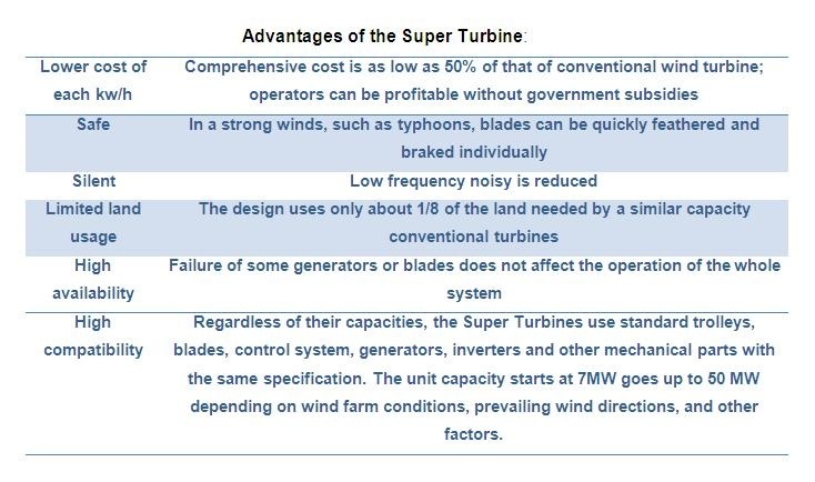
Editor's Choice - Super Turbine offers an alternative to conventional designs
Conventional wind turbines are generally grouped into horizontal axis wind turbines which have their main shafts deployed horizontally, and vertical axis wind turbines which have their main shafts deployed vertically. Current horizontal axis wind turbines of different designs are manufactured separately so that parts for different models and specifications are usually not interchangeable. In addition, the blade, nacelle, and tower are huge, making installation and maintenance difficult and expensive.
Up-sizing vertical-axis wind turbines, however, also produces barriers. First, it’s difficult to upsize the main shaft. Although it is often a hollow-tube truss, a large main shaft can be difficult to manufacture. Second, blade-connection parts for vertical axis wind turbines are typically cantilevers. When the turbine rotates, the cantilevers are subject to centrifugal force and alternating loads. Therefore, blade connection parts must be strong, influencing the turbine’s performance and cost. And third, because of the first two factors, vertical axis wind turbines (VAWTs) are not upsized easily, making their cost difficult to reduce.
The physics of VAWTs
For fixed-pitch VAWTs, when the rotor spins, the magnitude and direction of torques generated on each blade change constantly. The sub-torque could be positive or negative, and larger or smaller depending on each blade’s position. Therefore, the torque of the wind rotor formed by sub-torques is not consistent, and this can lower the design’s efficiency.
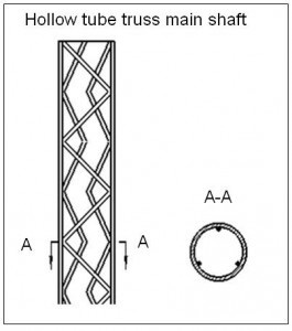
Conventional VAWTs require a complex and expensive center shaft to support the structure
To increase the efficiency of VAWTs, it is necessary to adjust blade angles based on blade position. To adjust blade angles, a blade pivot is usually deployed on the blade chord to let the blade rotatable around a pivot. This adjusts blade angles and increases turbine efficiency. Some call this a “real time, active-pitch technique.”
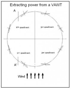
A top view of a VAWT describes four quadrants. Blades in the first and fourth extract the most power from the wind.
However, even if the angles of all blades are optimized to get a maximum driving force, the energy extracted by each blade varies greatly in magnitude depending on its position in orbit. For example, in extracting power from a VAWT, the blade outputs maximum torque only at most positions in the first and fourth quadrants. Is there a way to extend the quadrants where the blade outputs the maximum torque to increase turbine efficiency? The answer is, yes.
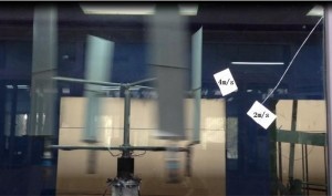
In the photo, the blades are individually controlled by a servo motor to an optimal degree. The rotor has a 1.36-m diameter, the blade (airfoil profile: NACA0009) is 1-m high and 260-mm wide. Using magnetic powder as resistance source, with a specially made cam curve (blade-angle range for blades at various positions), under a wind speed of 2 m/s, the rotor rotation speed tested at 44 rpm while providing a torque of 0.9 to 1.0 Nm. The wind-energy-to-mechanical-energy conversion efficiency reached 68%, exceeding the limit of 59.3% of Betz’s Law.
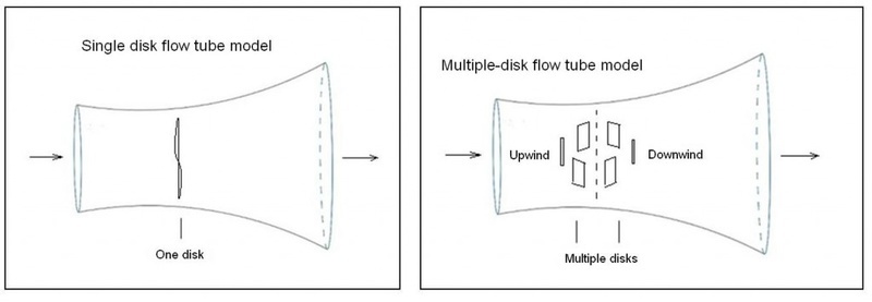
Betz law refers to single disk wind turbines. Designs sufficiently large and with multiple disks can theoretically exceed the limit
However, this is not to say Betz’s Law is wrong. Betz described the movement of a two-dimensional single disk in the fluid field (Single disk flow tube model). However, the movement of a vertical axis winds turbine amounts to multiple two-dimensional disks moving in the fluid flow (Multi-disk flow tube model). So if the upwind and downwind disks work along the same direction, turbine efficiency could exceed the limit of Betz’s Law.
In wind tunnel tests, when wind speed increases, so does the rotor rotation speed. But the rotor efficiency decreases. The reason is that when the wind reaches the downwind third and the fourth quadrants, its speed in downwind area reduces with the increase rotational speed.
A proposal for a new design
Due to its unique characteristics, wind speed can be gradually recovered to the inflow velocity, Vo, after passing over an object. Now assume the diameter of the wind rotor is infinitely large and the blades are located relatively low. After the wind passes over the upwind blades, the wind speed recovers gradually to inflow velocity. When the wind arrives the downwind side, the blades there encounter the same velocity the upwind blades encountered earlier. As displayed in Extracting power from a VAWT, the blades at most positions in the first and fourth quadrants extract the greatest power. If we separate the rotor at line A-A and extend the rotor to A’-A’, we now have two half circles connected by a rectangle (A design for the Super Turbine) and all the blades in the A-A’ sections will extract the biggest power. This is the basic principle of the super turbine. It is based on real time, active-pitch technique for vertical axis wind turbines.
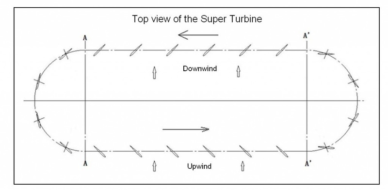
A top view of the proposed design shows its shape and scale, some 2,200-m long. The design expands on the quadrants one and four.
The key design of the super turbine is that the angle of each blade on a fixed track can be automatically adjusted based on blade’s positions, wind direction and speed, making a group of chained blades move along the same direction and driving a number of small high-speed generators on the track to generate electricity. All the currents are combined and fed to a medium sized inverter and then to the grid.
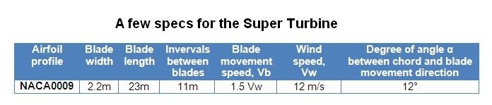
According to wind tunnel tests and CFD calculations, if the above parameters are adopted, the output from all blades in sections A-A’ is up to 143 kW (each blade includes an upper unit and a lower unit). Angle α changes with the change of wind direction, and angle α is usually two times of angle β. If wind direction rotates 45 degrees counter-clockwise, angle α will decline. Blade output efficiency varies with the change of wind direction.
For a super turbine with a line length (A-A’) of 2,200 meters, the line length (A-A) of 200 meters, 400 blades (each blade includes an upper unit and a lower unit), and an estimated system efficiency loss of 30% considering factors such as tracks, chain, generators, and others, its output can reach 40 MW under a wind speed of 12m/s.
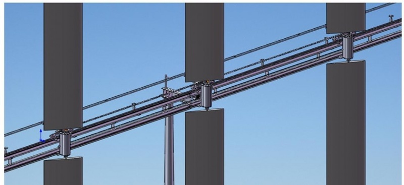
A close up of the trolley show some detail of the design.
When a blade runs through an entire circle on the track, it could be subject to winds from as many as six different directions. To ensure there is only rolling friction but no sliding friction when the trolley moves on the track (no sliding friction) any upwind or downwind position the track must resist forces from three different directions, as well as a full dynamic load under wind speed of 30 m/s. A conventional light train track may be adopted.
Electricity must be transmitted to each moving trolley to adjust its blade angle. Therefore, slip rings are used for transmitting the current to each moving trolley. Such current-collecting technology can be accomplished with a pantograph.
A hydraulic motor may be used to rotate blades. Assuming the track radius is at least 100 meters and the wind speed is 12m/s, the blade speed is only 65km/h, and the angular speed of blade around the blade pivot would be quite slow. The hydraulic motor meets the requirements.
Giving each trolley a unique code (001, 002, 003……….400), placing a photoelectric sensor every 10 degrees on the arc track, when a coded trolley (with its blade) passes through photoelectric sensors, the trolley’s position at the arc track is determined. Based the trolley’s position and wind direction, the motion controller adjusts the angle for each individual blade, the trolley then gets forward driving force.
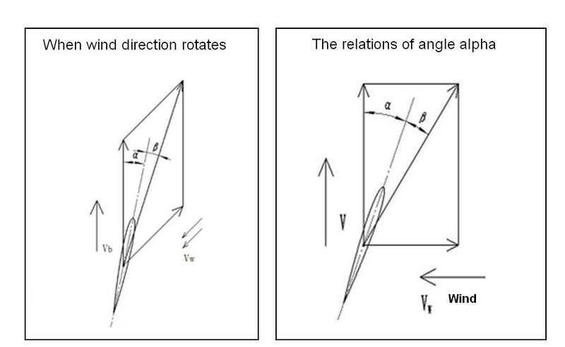
(left) When the wind direction rotates 45° counterclockwise, angle alpha will decrease. (right) Angle alpha, between the blade chord and direction of blade motion, is 12°.
Alternatively, each trolley (with its blade) may be controlled separately by an auto pilot that adjusts the blade angle. In this case, an anemoscope is needed on the top of each blade to identify current wind direction, and it then sends the information to the auto pilot to adjust the blades angle.
Available technologies
Existing technologies available for the super turbine include:
- Track technology
- Current collecting technology
- Hydraulic technology
- Encoding technology
- Wireless positioning technology
- Motion control technology, and
- Wireless signal transmission technology
To receive more information on this article, our Newsletter or find out more about what w3.windfair.net has to offer, please, do not hesitate to contact Trevor Sievert at ts@windfair.net.
Please don't forget to follow us on Twitter: w3.windfair.net on Twitter
w3.windfair.net is the largest international B2B internet platform in wind energy – ultimately designed for connecting wind energy enthusiasts and companies across the globe.
- Source:
- Qiang Yan (John Yan), Super Turbine Inc., Shanghai, China
- Author:
- Edited by Trevor Sievert, Online Editorial Journalist / by Qiang Yan (John Yan), Super Turbine Inc., Shanghai, China
- Email:
- ts@windfair.net
- Link:
- w3.windfair.net/...